Difference between revisions of "Autopilot Tripoke"
| Line 54: | Line 54: | ||
An attachment for the [[Uses Schematic::Autopilot Hex Panel Tripoke]] (and [[Used With::Autopilot Behavior Box]]) to sense pokes, deliver rewards, and deliver feedback with an RGB LED to mouse-sized animals. | An attachment for the [[Uses Schematic::Autopilot Hex Panel Tripoke]] (and [[Used With::Autopilot Behavior Box]]) to sense pokes, deliver rewards, and deliver feedback with an RGB LED to mouse-sized animals. | ||
| + | |||
| + | Gather your materials! | ||
| + | |||
| + | [[File:Autopilot_panel_build_1.jpg|class=img-responsive]] | ||
== Prepare PCB == | == Prepare PCB == | ||
| Line 71: | Line 75: | ||
[[File:cutting_pcb.mp4|class=vid-responsive]] | [[File:cutting_pcb.mp4|class=vid-responsive]] | ||
| + | |||
| + | == Soldering == | ||
| + | |||
| + | === Resistors === | ||
| + | |||
| + | The board uses 200 Ohm resistors (adjust depending on what LED you use) to limit current to each of the channels in the LED and to the IR transmitter in the beam break sensor. This board is designed for through-hole components to make it easier to assemble, so start by folding the legs of the resistors parallel and placing them through the line of holes on either side of where the ribbon connector will be. Pull the legs of the resistors through with needle nose pliers to get them to lie flat. | ||
| + | |||
| + | [[File:placing_resistors_cut.mp4|class=vid-responsive]] | ||
| + | |||
| + | Place the board in a third hand, flip it over, splay the legs of the resistors to either side, and solder | ||
| + | |||
| + | [[File:solder_resistors_cut.mp4|class=vid-responsive]] | ||
| + | |||
| + | Trim the legs with wire cutters. | ||
| + | |||
| + | === Socket === | ||
| + | |||
| + | Place the socket through the center holes on the same side as the resistors, notch side away from the center of the board. This usually seats it snugly enough to solder, but if it doesn't, hold it in place while you solder one or two legs, and then you should be able to let it go. | ||
| + | |||
| + | [[File:solder_plug.mp4|class=vid-responsive]] | ||
| + | |||
| + | == Assembling Cap == | ||
| + | |||
| + | Push the IR beam break sensor, LED, and [[Autopilot Nosepoke Needle Holder|needle holder]] into the [[Autopilot Nosepoke Cap|cap]] in the order shown: | ||
| + | |||
| + | [[File:tripoke_assembly_order.png|class=img-responsive]] | ||
Revision as of 03:36, 26 May 2022
A panel of three mouse-sized nosepokes to sense behavioral input, for delivering water reinforcements and, give task feedback via an RGB LED
| Modality | Reinforcement, Sensors, Enclosures |
|---|---|
| Build Guide Type | Electronics Build Guide |
| Creator | Jonny Saunders |
| Version | 1 |
| Submitted Date | 2021-07-07 |
Ingredients
Materials
| Name | Quantity | Dimensions | Manufacturer | Product ID | Price | Page | Datasheet |
|---|---|---|---|---|---|---|---|
| Hypodermic Needle | 3 | 18ga | BD | PrecisionGlide | 0.2 | [1] | |
| Machine Screw | 10 | #4-40, 5/8" | |||||
| Nut | 10 | #4-40 | |||||
| RGB LED | 3 | 5mm | |||||
| Resistor | 12 | 200 Ohm |
Tools
| Name | Tool Kind | Dimensions | Manufacturer | Product ID | Datasheet |
|---|---|---|---|---|---|
| 3D Printer | CAD Fabrication | ||||
| Dremel | Hand Tools Etc. | ||||
| Drill | Drill | ||||
| Needle Nose Pliers | Hand Tools Etc. | ||||
| Soldering Iron | Electronics | ||||
| Wire Cutter | Hand Tools Etc. |
An attachment for the Autopilot Hex Panel Tripoke (and Autopilot Behavior Box) to sense pokes, deliver rewards, and deliver feedback with an RGB LED to mouse-sized animals.
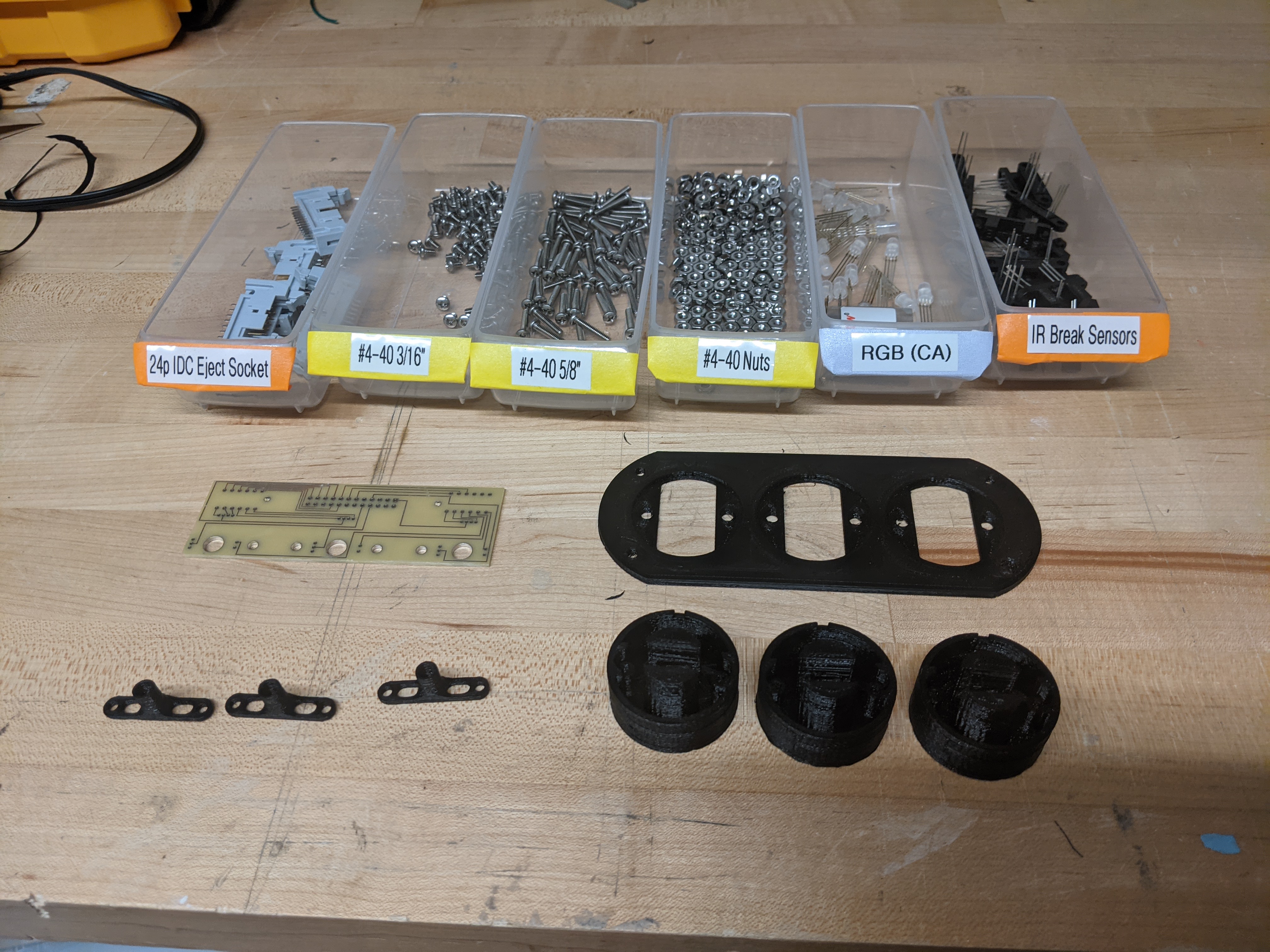
Gather your materials!
Prepare PCB
Cut In Half
When ordered from ExpressPCB, the Tripoke PCB comes with two boards on a single piece of silicon. First, cut them in half. With a ruler, mark a center cut line, and then follow it carefully with a cutoff wheel (like [2]) on a dremel.
Safety note:
- You should wear a respirator when cutting silicon to avoid silicosis
- you should also be careful to not put any pressure on the cut-off wheel orthogonal to the direction it spins. The wheels can shatter, and while they are light, they can do damage to your eyes and hands.
- Always wear safety goggles when using a dremel!
- Always think about escape routes when using power tools: hold the piece so that if it were to catch, it would pull it or you away from the tool, instead of into it.
Soldering
Resistors
The board uses 200 Ohm resistors (adjust depending on what LED you use) to limit current to each of the channels in the LED and to the IR transmitter in the beam break sensor. This board is designed for through-hole components to make it easier to assemble, so start by folding the legs of the resistors parallel and placing them through the line of holes on either side of where the ribbon connector will be. Pull the legs of the resistors through with needle nose pliers to get them to lie flat.
Place the board in a third hand, flip it over, splay the legs of the resistors to either side, and solder
Trim the legs with wire cutters.
Socket
Place the socket through the center holes on the same side as the resistors, notch side away from the center of the board. This usually seats it snugly enough to solder, but if it doesn't, hold it in place while you solder one or two legs, and then you should be able to let it go.
Assembling Cap
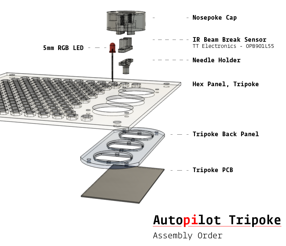
Push the IR beam break sensor, LED, and needle holder into the cap in the order shown:


