Difference between revisions of "GPIO"
(Created page with "== Pinout == thumb|660x660px == Power == Each GPIO pin runs at +3.3V and can safely source 16mA. Combined, they can source 50mA. There is no over-volta...") |
|||
| (One intermediate revision by the same user not shown) | |||
| Line 1: | Line 1: | ||
| − | + | ||
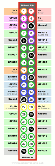
[[File:RPi_GPIO.png|thumb|660x660px]] | [[File:RPi_GPIO.png|thumb|660x660px]] | ||
| Line 14: | Line 14: | ||
More detail can be found [https://www.scribd.com/doc/101830961/GPIO-Pads-Control2 here], as well as in the [https://www.raspberrypi.org/wp-content/uploads/2012/02/BCM2835-ARM-Peripherals.pdf datasheet], which has some of the specifications pulled out [http://elinux.org/RPi_BCM2835_GPIOs here] | More detail can be found [https://www.scribd.com/doc/101830961/GPIO-Pads-Control2 here], as well as in the [https://www.raspberrypi.org/wp-content/uploads/2012/02/BCM2835-ARM-Peripherals.pdf datasheet], which has some of the specifications pulled out [http://elinux.org/RPi_BCM2835_GPIOs here] | ||
| + | |||
| + | == Interfaces == | ||
| + | |||
| + | === Memory Mapping === | ||
| + | |||
| + | * [https://www.cs.uaf.edu/2016/fall/cs301/lecture/11_09_raspberry_pi.html Raspberry Pi gpio via mmap] - an example of directly writing to the GPIO pins with mmap. This is how [[pigpio]] interacts with [https://github.com/joan2937/pigpio/blob/c33738a320a3e28824af7807edafda440952c05d/pigpio.c#L7335 gpio pins] | ||
| + | |||
| + | === Sysfs === | ||
| + | |||
| + | * The [[Rust]] GPIO package [[Has Rust Crate::gpio]] uses [[sysfs]] to access the pins! | ||
Latest revision as of 05:03, 2 April 2022
Power
Each GPIO pin runs at +3.3V and can safely source 16mA. Combined, they can source 50mA. There is no over-voltage protection on the pins, and they are not current limited, so be sure to test any connections with a voltmeter before making them.
The 5V rail can source as much amperage as is provided by the power supply minus that used by other peripherals and the Pi itself. Be mindful about overdrawing it, though, as underpowering the Pi causes it to skip cycles and ultimately crash.
Because the logic is obviously never going to be perfectly 0V = Low, 3.3V = High, the transition is determined by the maximum Low and the minimum High voltages:
- Maximum Low Voltage: 0.8V
- Minimum High Voltage: 1.3V
So there is some hysteresis, when the voltage drops below 0.8V it will register as Low, and will continue to read Low only until it reaches higher than 1.3V.
More detail can be found here, as well as in the datasheet, which has some of the specifications pulled out here
Interfaces
Memory Mapping
- Raspberry Pi gpio via mmap - an example of directly writing to the GPIO pins with mmap. This is how pigpio interacts with gpio pins
