Tripoke PCB
| Tripoke PCB | |
|---|---|

| |
| Modality | Reinforcement |
| Schematic Type | PCB |
| Description | double-PCB that powers three nosepokes worth of RGB LEDs and IR beam break sensors |
| Creator | Jonny Saunders |
| Version | 2 |
| Date | 2021-07-07 |
| Repository | |
| Git Hash | |
| Used In: | Autopilot Tripoke |
| Remixes: | |
| Tripoke PCB | |
|---|---|
| Manufacturer | ExpressPCB |
| Number of Layers | 2 |
| Dimensions (width;height) | 3.8" (2.5")
|
| Other Files | File:tripoke_pcb_double.rrb |
| Designed With Program | ExpressPCB Classic |
This board, along with the Needle Holder, Nosepoke Cap and Tripoke Panel are assembled to make the Autopilot Tripoke. See the Autopilot Tripoke build guide for more information about using this PCB.
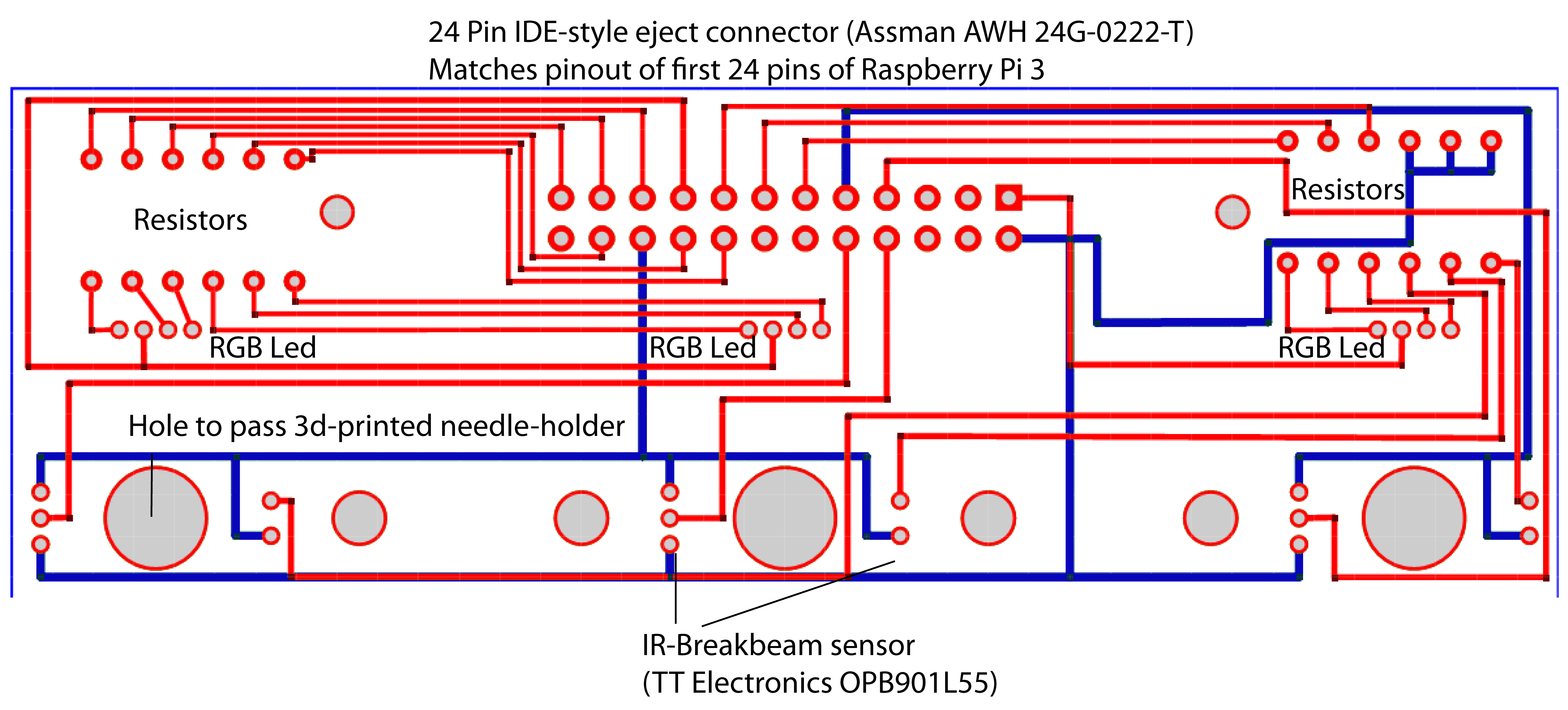
It has the rather unfortunate quality of being designed in ExpressPCB's proprietary software and format, but can relatively easily be reconstructed from the images provided.
The schematic as provided makes two boards on a single 3.8" x 2.5" board, which costs $65 for a set of three, each of which has two sub-boards on it -- or each one of the 6 boards costs $10.80.
To separate the boards, use a Dremel with a standard cutoff bit and cut along the center line.
Annotated Schematic
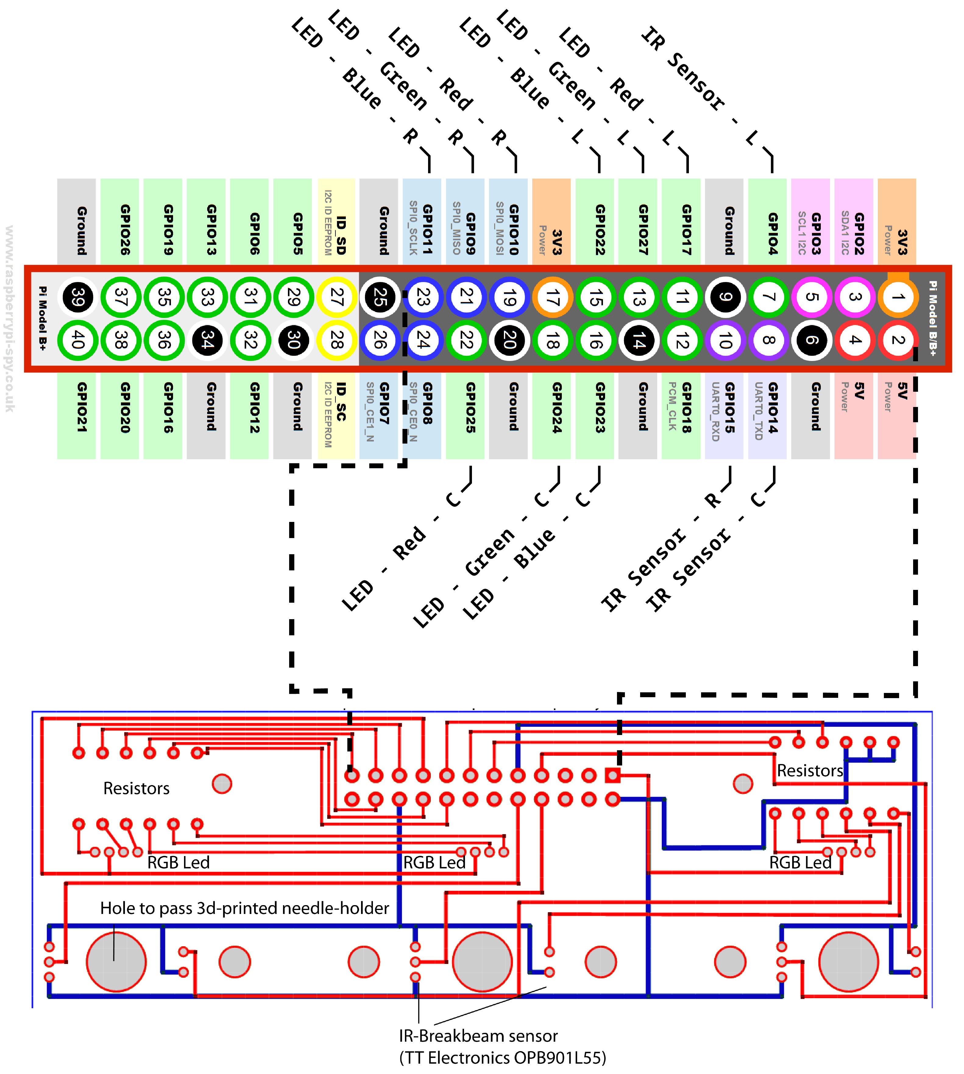
As an overview, the board is intended to distribute the 5V and 3.3V power supplies of the Raspberry Pi 4 to three RGB LEDs and IR beam break sensors, and return the digital logic signal from the beam breaks. A pinout is provided below
- A 24-pin header is soldered to the top rows of pins, I recommend using an IDE-style connector with eject latches (like the Assman AWH 24G-0222-T) to avoid it being a huge pain to work with.
- Through-hole resistors are soldered to the board in groups of six for 12 total in the top slots labeled "Resistors". The value of the resistor depends on the particular LEDs and IR beam break sensors you use.
- Three IR beam break sensors are soldered in the lower groups of five holes, this board in particular was designed for the TT Electronics OPB901L55.
Pinout
| Pin (board number) | Use | Poke |
|---|---|---|
| 1 | 3.3V | |
| 2 | 5V | |
| 7 | IR beam break input | Left |
| 8 | IR beam break input | Center |
| 9 | Ground | |
| 10 | IR beam break input | Right |
| 11 | LED - Red | Left |
| 13 | LED - Green | Left |
| 15 | LED - Blue | Left |
| 16 | LED - Blue | Center |
| 17 | 3.3V | |
| 18 | LED - Green | Center |
| 19 | LED - Red | Right |
| 20 | Ground | |
| 21 | LED - Green | Right |
| 22 | LED - Red | Center |
| 23 | LED - Blue | Right |

